

"A car's steering is its soul. It communicates the intentions of the driver to the machine." - Enzo Ferrari
The Tesla Cybertruck has stirred up controversy in the automotive world long before customers got their hands on it. It defies all conventional car design norms with sharp angles and geometric shapes. The body is made from flat, ultra-hard 30X cold-rolled stainless steel panels. Their decision to build on a unibody car design (body and chassis is a single part) versus a body-on-frame (frame attached to underlying chassis) marks another significant departure.
For the obvious physical changes above, arguably the most important difference is in the internals of the car: the shift in steering technology. Instead of a traditional mechanical system, the Cybertruck adopted steer-by-wire where pure electronic controls replace the mechanical connection between the steering wheel and car wheels. It’s a complete physical disconnect between the wheel you hold, and the wheels of the car!
In the next sections, we'll dive into a brief history of steering and explore how steer-by-wire actually works (Tesla’ Patent Application: WO2023107555A1). We’ll address how we arrived at steer-by-wire, safety concerns when you remove physical linkages, and implications for future cars.
Steering Technology Evolution
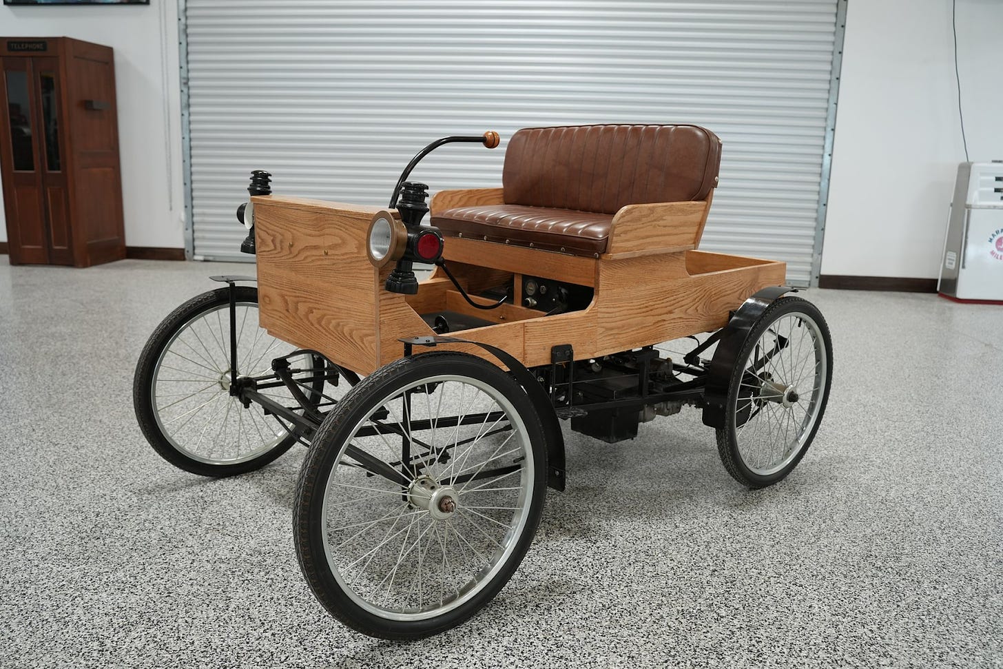
In every moment of driving, one of the primary feedback channels comes from steering. Steering technology has advanced significantly since the early days of mechanical linkages. In the 1900s, early vehicles used a tiller—a simple lever that pivoted the front wheels. While functional, it was limited in precision and control.
Mechanical Steering
The fundamental components of any mechanical steering system are:
- Steering Wheel: Rotational motion is initiated by the driver.
- Steering Column: Shaft connects steering wheel to the steering mechanism. When the wheel is turned, the steering column transfers this rotational motion down to the pinion gear.
- Pinion: Small gear at the end of the steering column. Main function is to convert the rotational motion from the steering column into linear motion.
- Rack: Linear gear that meshes with the pinion gear. When the pinion gear turns, it moves the rack left or right. This linear movement of the rack translates into the turning of the vehicle's wheels, allowing the car to change direction.
- Tie Rod: Located at the end of the rack, it connects to the steering arm. Ensures that the linear motion of the rack is accurately translated into the correct new direction for the wheels.
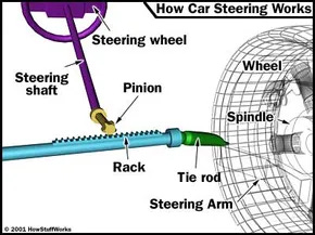
When the driver turns the wheel, this rotational motion is transferred to the pinion gear through the steering column. The pinion gear then meshes with the rack (linear gear) to adjust the angle of the tires for turning. A tie rod at the end of the rack connects to the steering arm, ensuring this linear motion accurately turns the wheels.
Older cars were often designed with larger steering wheels that provided more mechanical advantage, and a longer throw, meaning each degree of steering wheel turn moved the steering linkage components a greater distance. This made it easier to turn the wheels in pure mechanical systems.
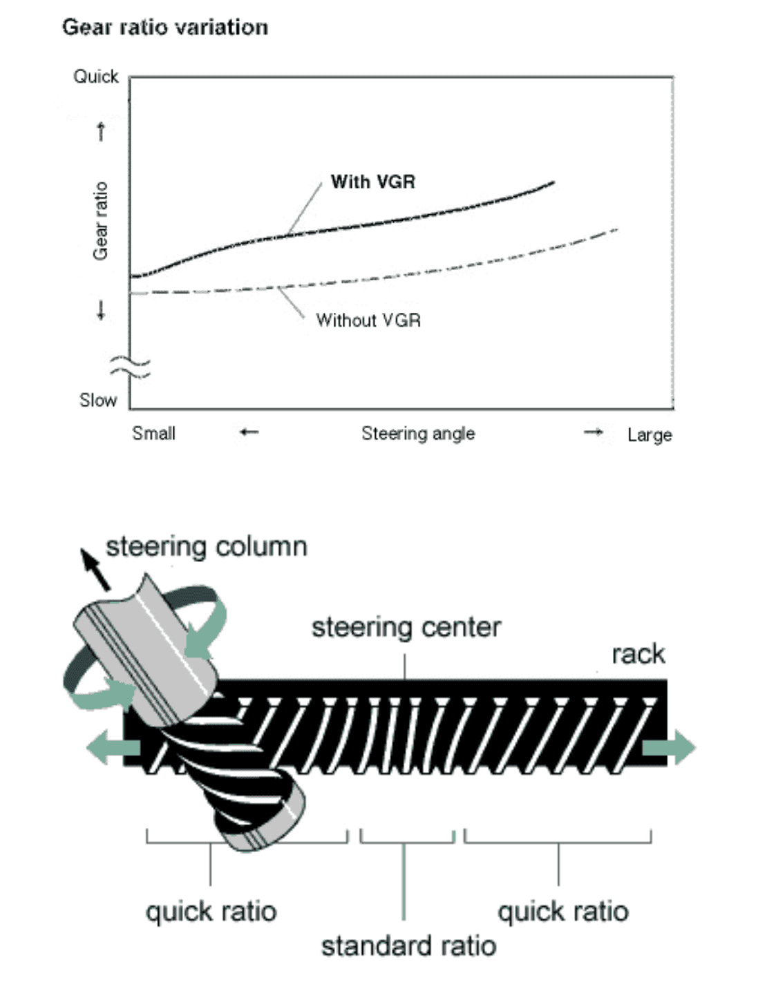
Some car designs use variable ratio steering, where there’s a varying tooth pitch (number of teeth) on the rack changes along its length. In the center, there are fewer teeth per centimeter compared to the ends. This design makes steering more responsive at maximum turn angles and less sensitive near the center, improving maneuverability.
Power Steering
The next major leap came in the 1950s with the introduction of power steering. Hydraulic power steering systems used a pump driven by the engine, to assist the driver in turning the steering wheel. This innovation made steering much easier, particularly at low speeds and parking. By the 1970s, power steering had become a standard feature in most cars.
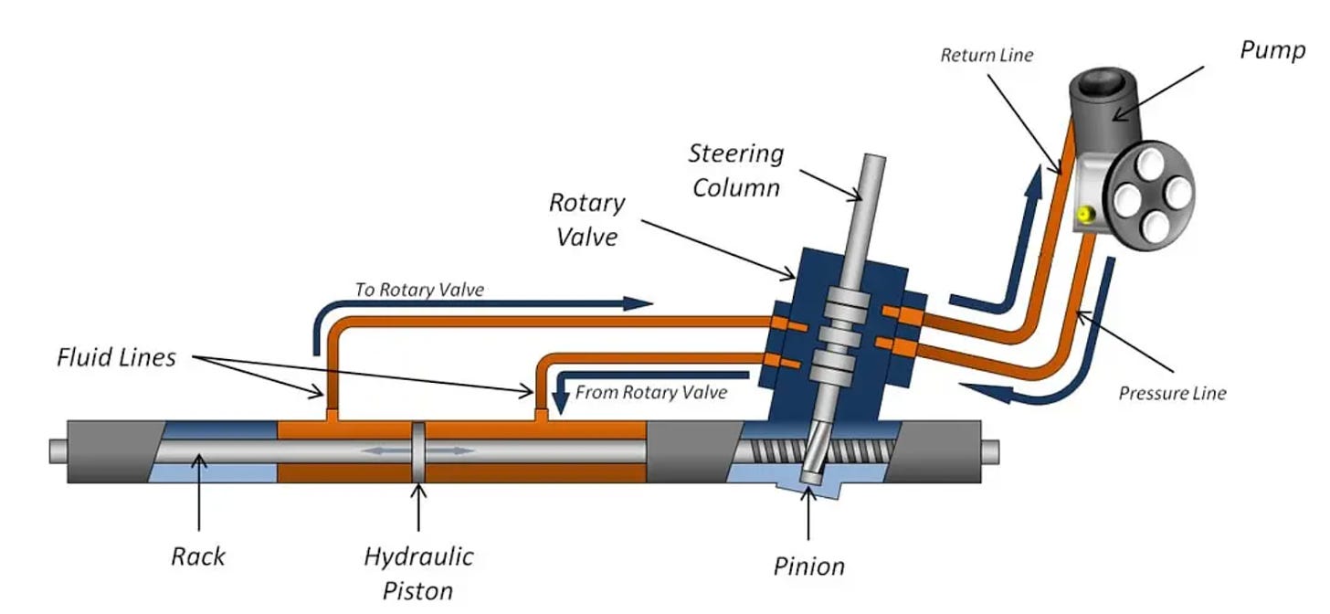
How it Works:
- Torsion Bar (Steering Column): Connects the steering wheel to the pinion gear in the steering column. When the driver turns the steering wheel, the torsion bar twists proportionally to the applied force.
- If the force exerted by the driver is insufficient to move the pinion gear, the torsion bar twists, causing a relative displacement between the inner and outer sections of the rotary valve.
- Valve Operation: This displacement opens specific passages in the rotary valve, directing high-pressure hydraulic fluid to one side of the hydraulic piston.
- Hydraulic Assist: The pressurized fluid exerts force on the hydraulic piston, which assists in turning the steering gear, thus reducing the manual effort required by the driver.
- Degree of assistance provided by the hydraulic system is proportional to the force applied to the steering wheel. Low speed has more assistance, high speed has less.
TLDR; a hydraulic piston that moves side to side with the steering rack. This video here provides a great explanation.
Electro-Hydraulic Power Steering
Hydraulic power steering offered better stability and handling, but came with several drawbacks. Since the pump was driven by the engine, there was high parasitic power consumption. At low engine speeds, the assist was weaker and in high-RPM motors, the pump often faced reliability issues.
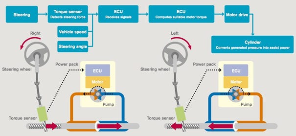
To fix these problems, electro-hydraulic power steering came into play. Here, an isolated electric motor powers the pump, and a torque sensor measures the force applied at the steering wheel. An electronic control unit (ECU) then figures out how much motor torque should be provided to the hydraulic piston. The addition of an electronic control unit (ECU) to handle sensor inputs meant that the car speed and steering angle could be inputted into more sophisticated control systems. These signals would aggregate to a calculated output motor torque, which would drive the pump and direct high pressure fluids to the desired side of the hydraulic piston.
Electric Power Steering:
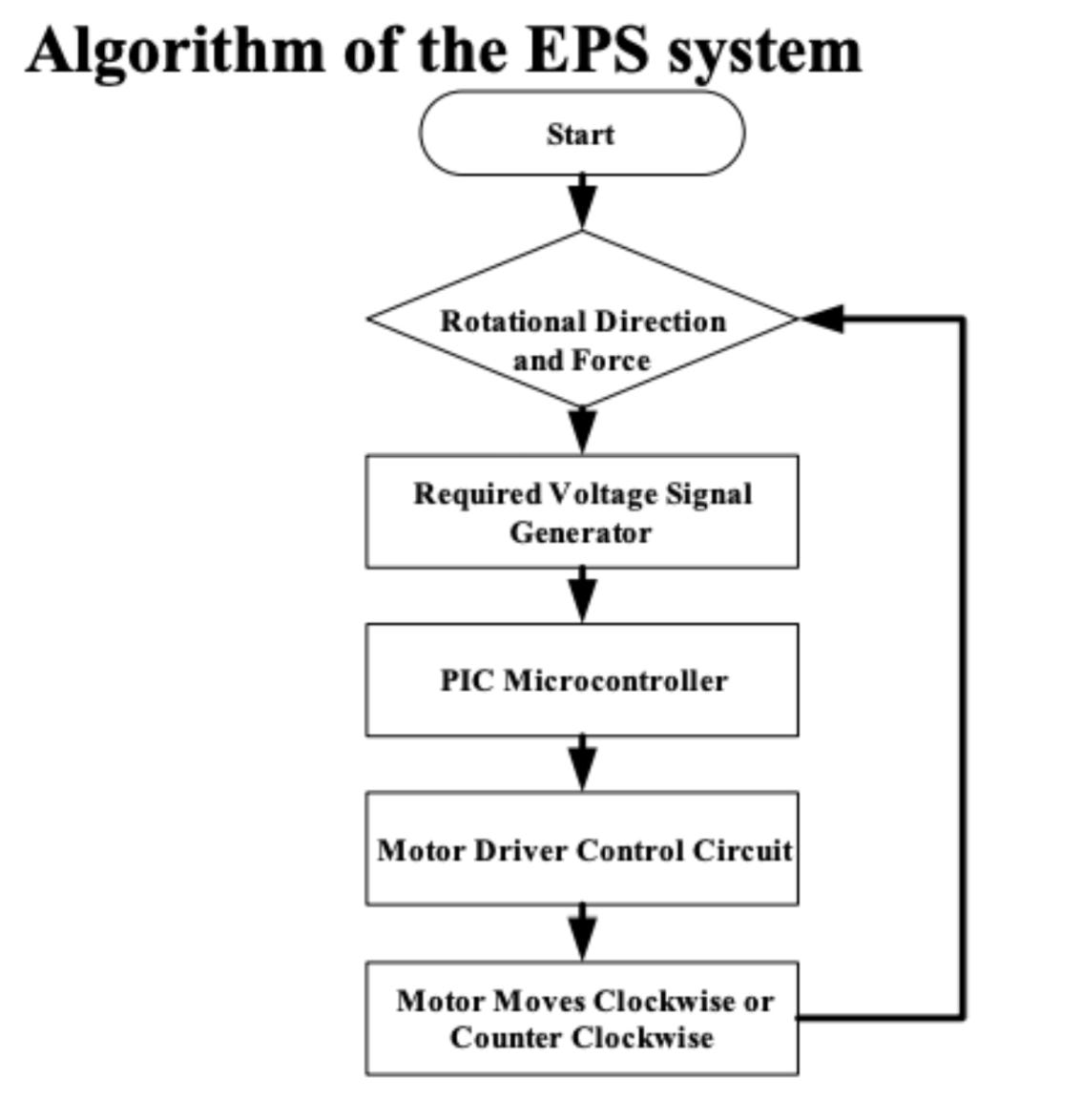
Since the late 1980s, electric power steering (EPS) has become the standard in cars. Unlike traditional systems that use a motor to drive a hydraulic pump, EPS connects the motor directly to the steering mechanism.
In rack and pinion setups, the motor can be placed in various positions:
- Steering Column: The motor is mounted on the steering column.
- Pinion: The motor is mounted at the gearbox where the pinion gear contacts the rack.
- Double Pinion: Two pinion gears move the rack. A second rack and pinion, integrated along the rack, has a motor for power assist.
- Steering Rack: The motor is connected directly to the rack, sometimes even concentric with it.
As the industry shifted toward electric power steering, both drivers and manufacturers gained advantages: EPS consumes just a fraction of the energy of traditional hydraulic power steering (~1/20th!), requires less maintenance due to the absence of hydraulic oil, and simplifies vehicle assembly.
Steer-by-Wire
Tesla’s move to eliminate the mechanical connection in the Cybertruck’s steering system is a step evolution forward in automotive technology. About a decade ago, Nissan introduced the first steer-by-wire system in the Infiniti Q50, but still had a mechanical backup linkage for safety. Until recently, regulations required a mechanical link for steering, but changes now allow for systems like Tesla’s.
This might seem radical especially when it comes to safety, but it aligns with Tesla’s engineering philosophy. Elon Musk’s 5-step approach comes into play when thinking through how their engineering teams rationalize design choices:
Question every requirement.Delete any part or process you can.Simplify and optimize.Accelerate cycle time.Automate.
How it Works:
The system can be broken down into two primary systems connected through wires instead of the traditional steering column:
- Steering Wheel Module
- Steering Rack Module
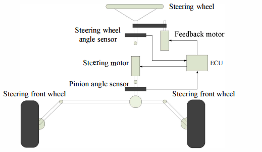
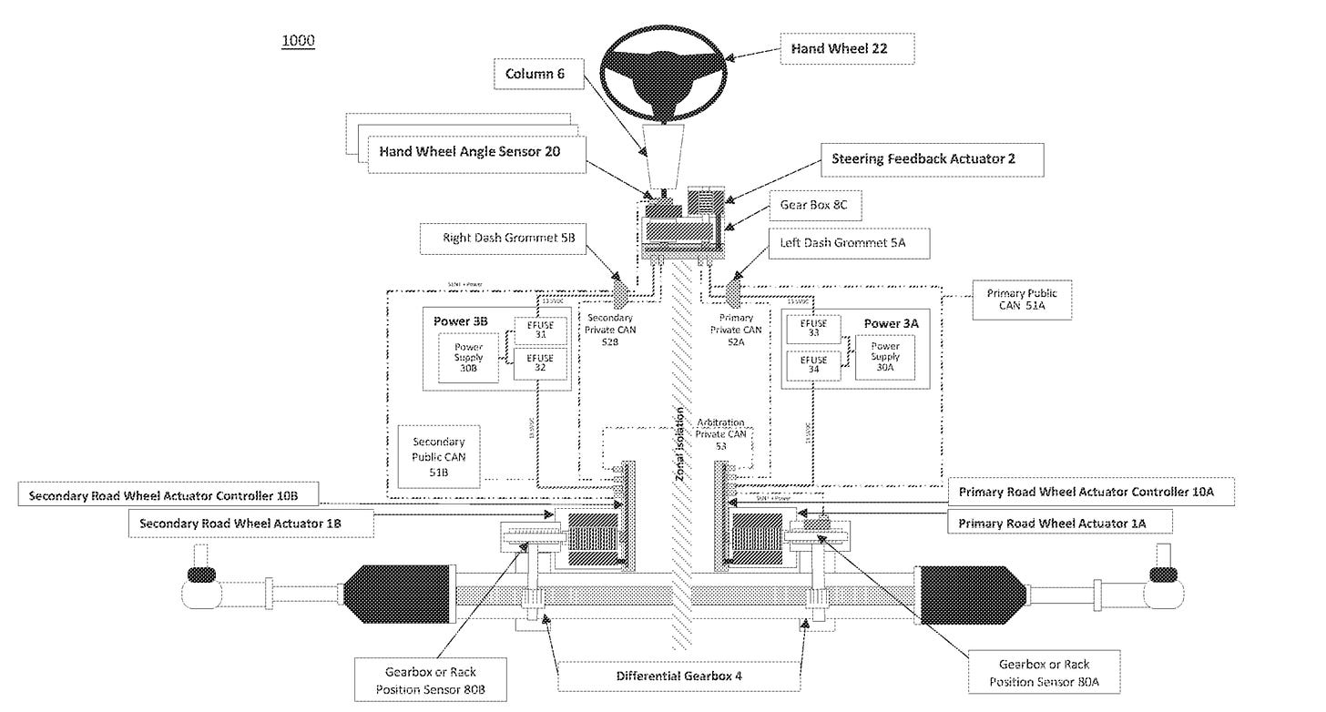
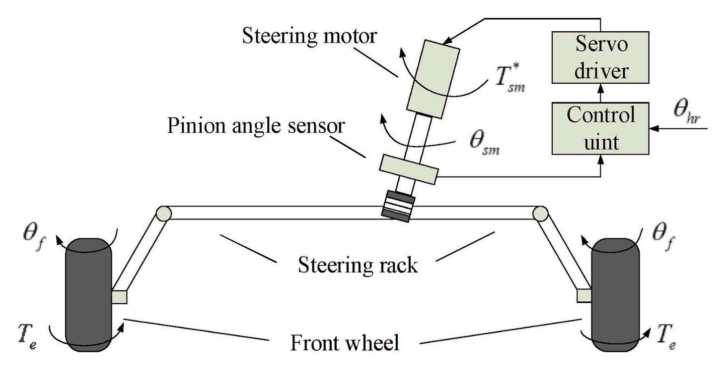
Steering Wheel Module: This unit consists of the steering wheel, steering wheel angle sensor, and a feedback actuator that provides a haptic road feeling force to the driver. The user imparts a torque, Th, that changes the angle of the steering wheel, 𝜃h. This angle, along with the angle of the front tires, 𝜃f, are sent to the control unit which computes a value for the feedback torque, Tr, to be sent to the driver to reflect road conditions.
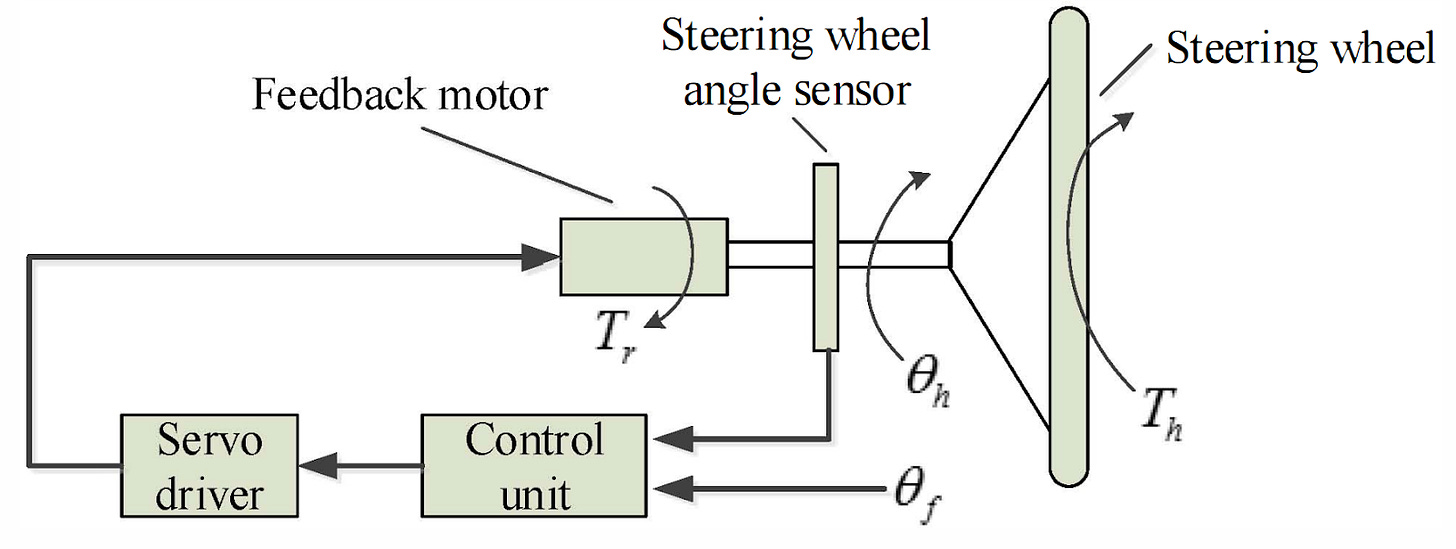
In the Cybertruck’s steering wheel module, a similar set-up is used, but with two separate controllers. In a situation where one controller fails, the system has a secondary controller to provide steering feedback.
Steering Rack Module: In the rack unit, the road wheel actuator, typically rated between 150 and 1000 W, operates based on commands from the ECU controller. The controller processes inputs from the steering system, along with data from speed sensors, accelerometers, angle sensors, and yaw rate sensors. The motor adjusts the tire angle accordingly, ensuring precise vehicle control. The processed sensor data also generates feedback signals for the steering feedback actuator.
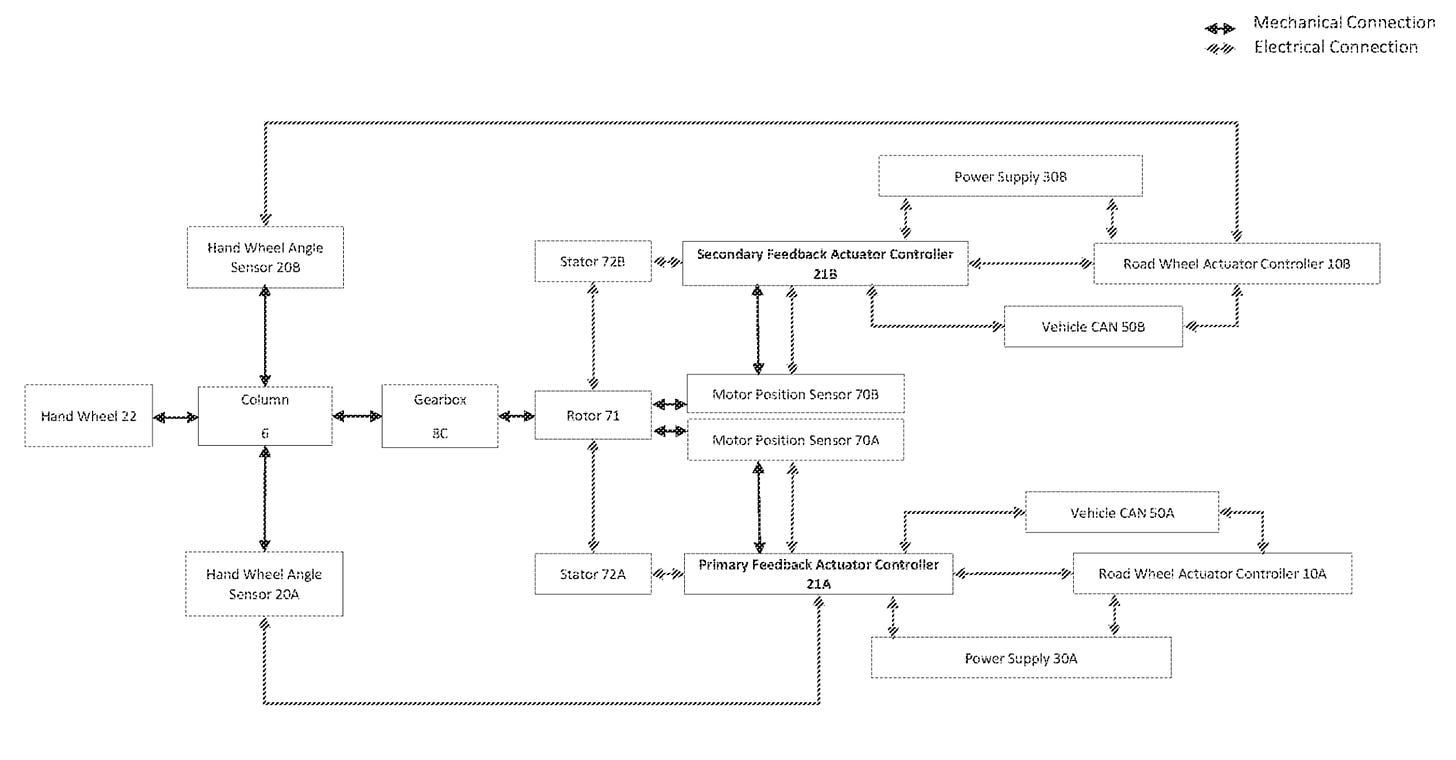
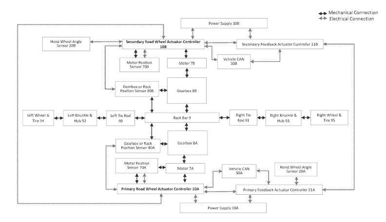
The steering rack module in the Cybertruck’s steer-by-wire system follows the same setup as described earlier, but with a design emphasis on redundancy and fault tolerance. It includes a primary and secondary road wheel actuator, each with its own magnetic position sensor, along with a third inductive position sensor for triple redundancy. This three-sensor architecture enables fault detection and isolation through a two-out-of-three voting mechanism.
The system is also designed with zonal isolation in mind, where the redundant components are physically separated to prevent a common fault from compromising the entire system. This isolation extends across the controllers, power assemblies, and communication networks, each of which is independently managed.
Specifically, the system integrates two zonally isolated motors and controllers for the front road wheels, ensuring that even if one motor or controller fails, the other can maintain steering functionality. The system’s architecture also includes three private communication networks between each node.
Safety Considerations:
With no physical link between the steering wheel and the road wheels, Tesla addresses this concern by building redundancy into every critical component. In the Cybertruck, position sensors are triple-redundant, and all other systems are double-redundant. This extends across power supplies, power converters, controllers, and Ethernet & CAN buses.
Over the course of our research, what we found most surprising is that aviation has been using fly-by-wire systems since the 1970s! It’s important to note that aircraft have mandated inspection requirements by the Federal Aviation Administration (FAA), but cars don't have the same stringent oversight.
Architecture Thoughts:
The primary reason for pursuing steer-by-wire, despite the immense engineering complexity involved in bringing it to mass production, was to enhance steering and handling in large vehicles like the Cybertruck.
Variable Steering Ratios: In traditional systems, the gear ratio between the rack and pinion dictates how much your tires turn when you steer. It’s fixed, no matter the speed. With steer-by-wire, there's no steering column, so the car can calculate the best ratio for any speed—high ratio at low speeds, low ratio at high speeds. Traditional steering wheels usually has a full turn angle of 1080°, but with steer-by-wire, that angle can shrink to 200°.
- In Tesla's Cybertruck, speed-dependent steering ratios enable it to turn with a much smaller radius compared to other trucks of the same length.
Rear-Wheel Steering: Tesla’s steer-by-wire system also utilizes software-controlled rear-wheel steering (as shown below). For comparison, the Ford F-150 Lightning has a turning circle of 47.8 feet, while the Cybertruck with a maximum rear-wheel turn angle of 3°, achieves a turning circle of 43.5 feet. Future software updates aim to increase this angle to around 10°, further reducing the turning circle and enabling even tighter turns.
Steer-by-wire is a glimpse into the future of automotive engineering—simplifying mechanics while unlocking new possibilities for control and handling. Time will tell how widely this steering technology is adopted, but it’s a clear next step in the evolution in steering technology.
Research Links:
- A Composite Control Scheme for Automotive Steer-By-Wire System by Xiaoxue Zhang, Huifang Kong, Hai Wang
- Tesla’s Patent Application: WO2023107555A1

