In the world of engineering, the battle to save weight without compromising on performance is a constant struggle. Enter Roboze, a trailblazing startup capturing the attention of industry giants like Leonardo and Saudi Aramco. With their innovative 3D printing technology and advanced material formulations, Roboze is revolutionizing the way engineers design rockets, airplanes, motorcycles and pipelines.
Imagine a material that's not only light but also incredibly strong, stiff, and resistant to extreme temperatures and harsh environmental conditions. This is the promise of Roboze Carbon PEEK, a proprietary carbon fiber reinforced super polymer (CFRP) that's setting new benchmarks in the industry. Roboze’s material science lab has developed a Carbon PEEK formulation with a carbon fiber content of 30% by weight, which is significantly higher than industry standards (10%). The density of the carbon fibers translates to weight savings of over 50% compared to metals, without losing out on strength or environmental, flame, and chemical resistance.
But the innovation doesn't stop at the material itself. Roboze's high-precision, beltless printers, featuring monstrous cubic meter chambers with flawless temperature control (+/- 5°C at any point), ensure that every print is as precise and reliable as it is strong. The result? A lightweight, accurate, and durable composite material that rivals the strength of metal.
Roboze analyzed the mechanical properties of both PEEK and Carbon PEEK. The findings, detailed below, provide a glimpse into the future of industrial production, where advanced materials and cutting-edge 3D printing technologies converge to push the boundaries of what’s possible.
Characteristics of PEEK & Carbon PEEK
Polyetheretherketone (PEEK) is a semicrystalline thermoplastic polymer belonging to the polyaryletherketone (PAEK) family. It is known for its excellent mechanical properties and chemical resistance, which it maintains over a wide temperature range (from 150°C to 250°C). These properties include self-lubrication, self-extinguishing, hydrolysis resistance, low outgassing, and dielectric properties, making it ideal for applications in the energy, aerospace, automotive, and electrical sectors.
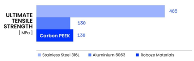
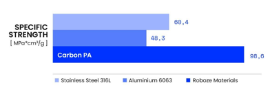
Roboze Carbon PEEK packs chopped carbon fiber into PEEK, which drastically improves the material’s strength and stiffness while preserving the benefits of PEEK. Early batches of Roboze Carbon PEEK already surpass the tensile strengths of some aluminum alloys like Aluminum 6063 in terms of specific strength (tensile strength/density). This allows Carbon PEEK to fully substitute Aluminum in the manufacturing industry
Challenges of Processing PEEK & Carbon PEEK
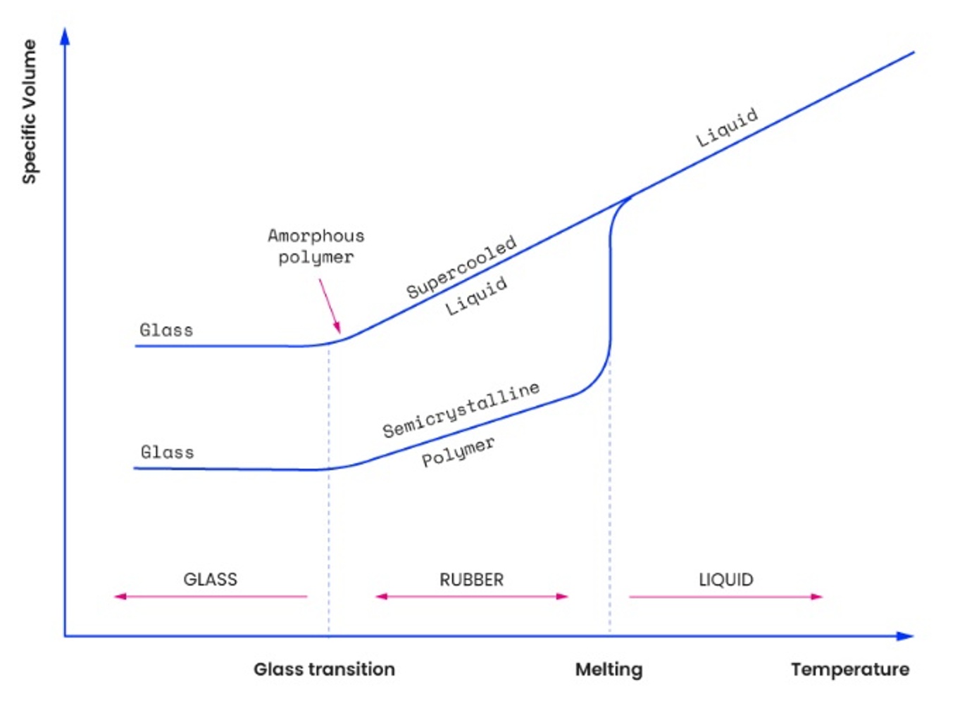
Processing PEEK with Fused Filament Fabrication (FFF) technology is complex due to the material’s high viscosity, high melting temperature, and semicrystalline nature. Semicrystalline polymers, such as PEEK, exhibit crystalline structures within an amorphous matrix. During the extrusion and cooling process, these structural differences cause volumetric contractions, leading to the formation of residual stresses, distortions, and weak interlayer bonding forces.
Components made using additive manufacturing technology have a structure characterized by layers of material interfaces and air gaps.
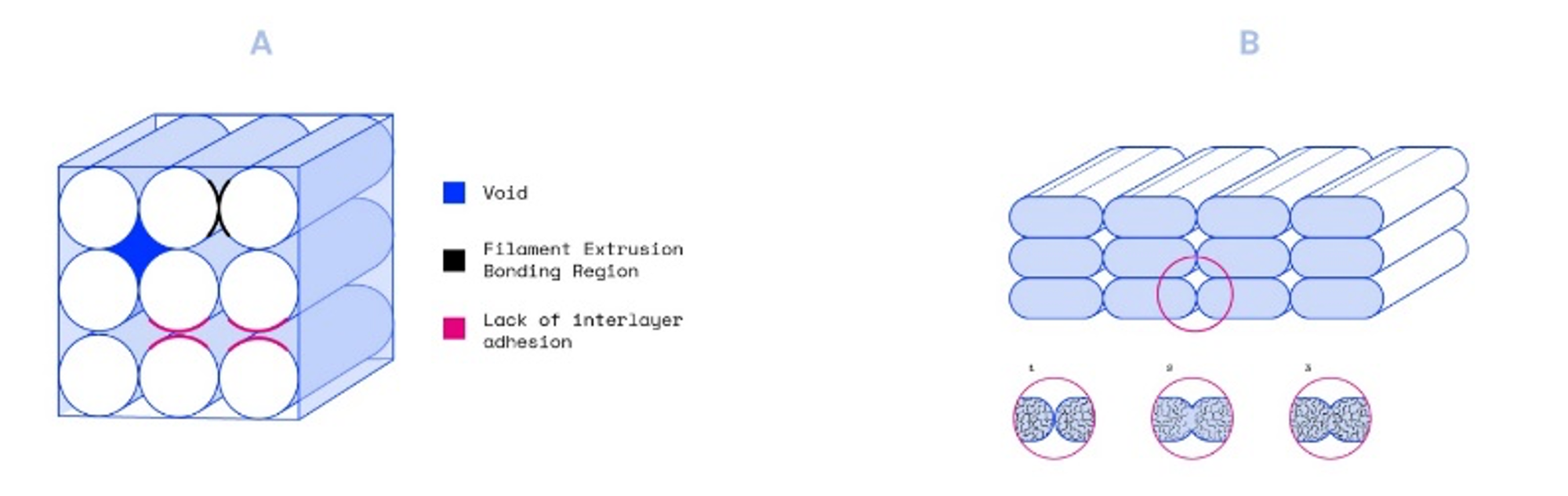
Interfacial adhesion between adjacent single filaments occurs through heat-induced molecular diffusion. The quality of the bond depends on the temperature of the surrounding environment and on the variations of the convective conditions inside the build chamber.
When the semi-fused filament is extruded through the nozzle, during the cooling phase, these ordered regions show a greater volumetric contraction than the amorphous component and a different shrinkage rate depending on the size and shape of the individual domains. These phenomena lead to the formation of residual stresses during cooling which can cause distortions, deformations, detachment of the piece from the printing surface, weak bonding force between the individual layers, high porosity and reduction of the section on which the load rests.
The Roboze’s printers utilize insulated stainless-steel chambers that ensure a homogeneous temperature throughout the printing volume. This uniform thermal distribution reduces the temperature difference between the extruded material (up to 450°C) and the external environment (up to 180°C), slowing down the cooling process and minimizing shrinkage forces and residual stresses.
Experimental Methods
The study was conducted using a Roboze ARGO 500 printer (dimensions: (X) 500 x (Y) 500 x (Z) 500 mm) equipped with a filament of 1.75 ± 0.05 mm diameter. The thermoplastic filament was extruded through a 0.6 mm diameter nozzle. To minimize the absorption of water molecules from the filament exposed to the atmospheric environment, the spool of polymer material was subjected to a drying cycle at 100°C for 12 hours in the HT Dryer (Roboze SpA, Italy) before starting the printing process.
Process Steps
Step #1: CAD Model Design: The FFF process involves the extrusion and subsequent deposition of a fused filament of polymeric material. The starting point is the CAD model of the object designed using modeling software.
Step #2: Mesh Generation and Print Job Preparation: After designing the solid model, it is necessary to discretize its surface by generating a stereolithographic file (*.stl). This format uses a series of interconnected triangles to recreate the geometric surface of the solid, the result of the discretization process known as "mesh." Once the *.stl file is generated, slicing software allows for setting up the print job by selecting the quantity and positioning of parts, organizing support structures, and defining process parameters. Each portion of the tower was identified with a unique code based on its position in the XY plane and along the Z-axis.
Step #3: Slicing and Loading the Machine File: Once the print job is defined, the slicing software applies the selected parameters, generating a series of instructions (*.gcode) compatible with the printer's machine language. After receiving the file, the component can be printed.
Step #4: Layer-by-Layer Construction of the Part: The printer reads the *.gcode file containing information about the layers into which the model has been divided and guides the layer-by-layer construction of the physical model. The thermoplastic filament is melted with the help of heat, extruded through a small-diameter nozzle, and then deposited layer by layer onto the printing platform. Following this process, five PEEK towers and five Carbon PEEK towers were obtained.
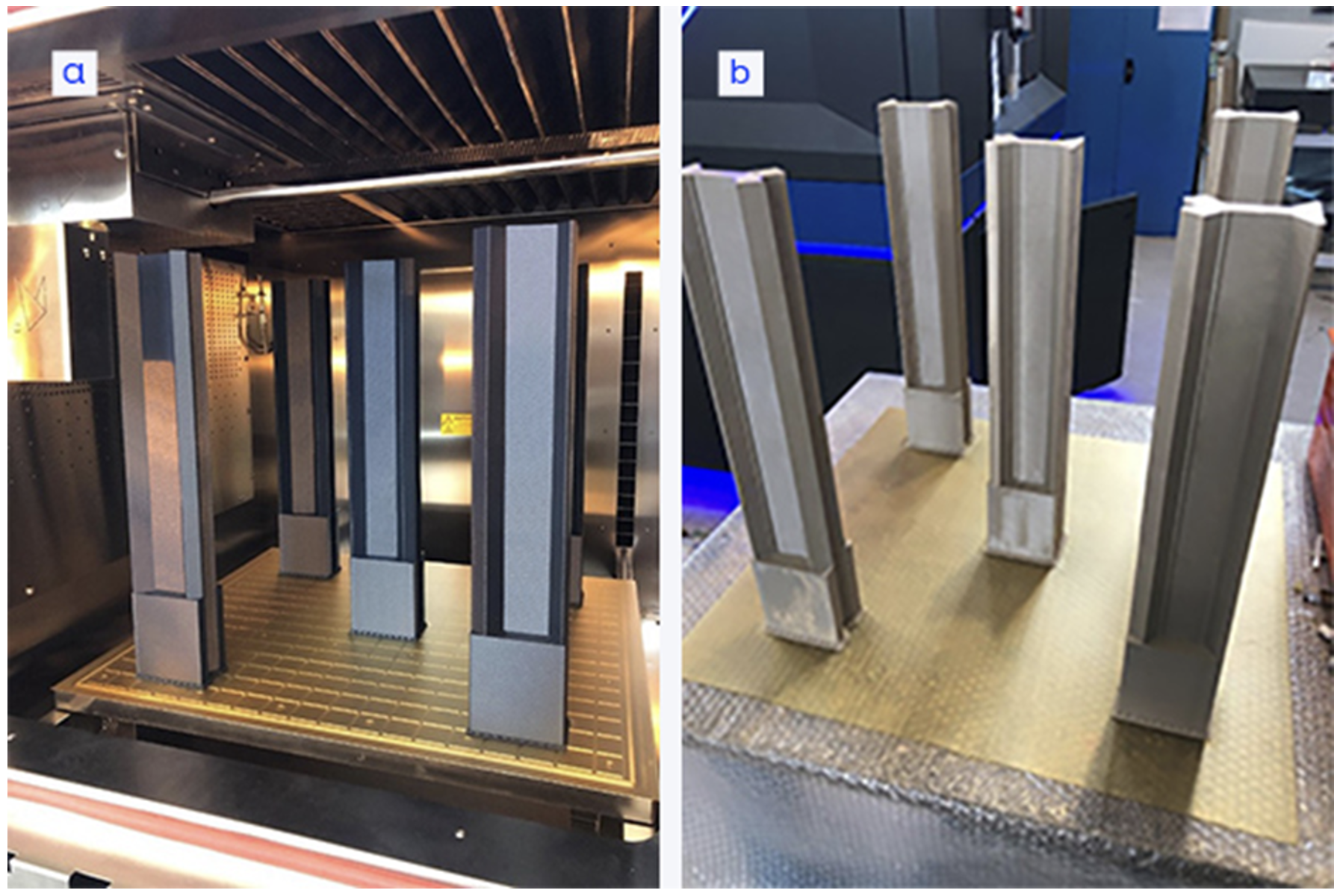
Step #5: Post-Processing: Once extracted from the build chamber, the printed part was removed from the build plate, and the individual towers underwent a milling process to obtain the specimens required for mechanical characterization. For each tower, specimens for compressive strength and modulus were obtained at different heights.
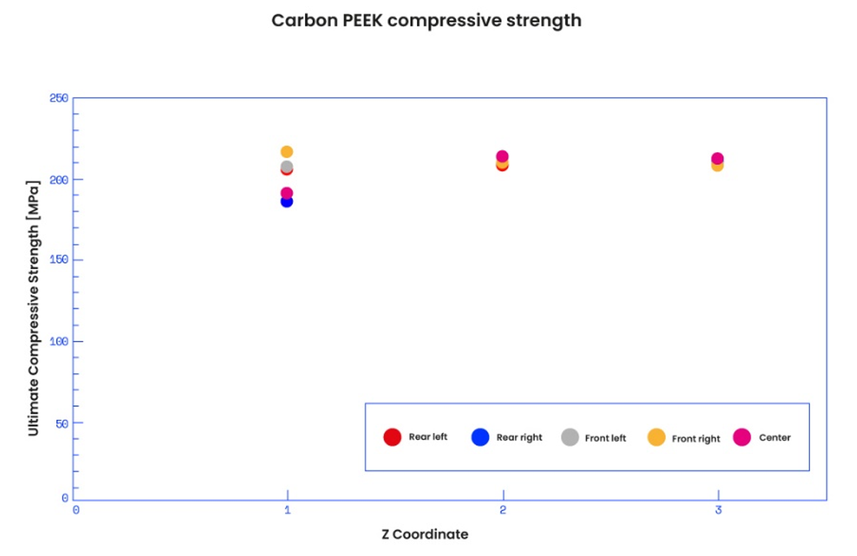
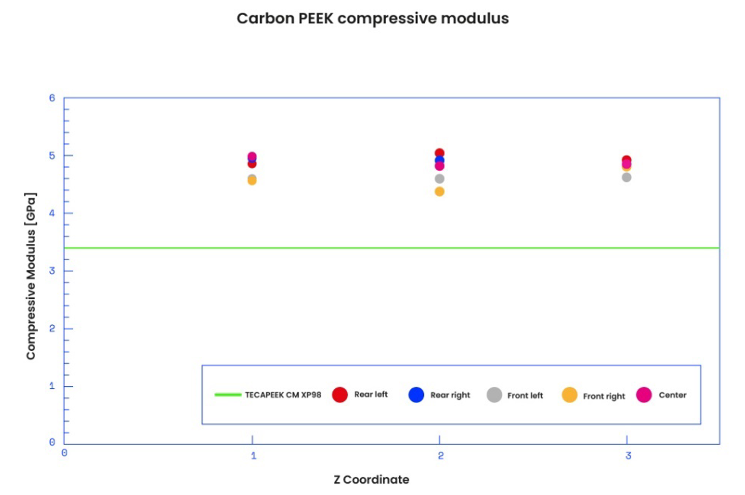
Conditioning and Measurement: In this way it was possible to map five different positions in the XY plane at three different heights along the Z coordinate.
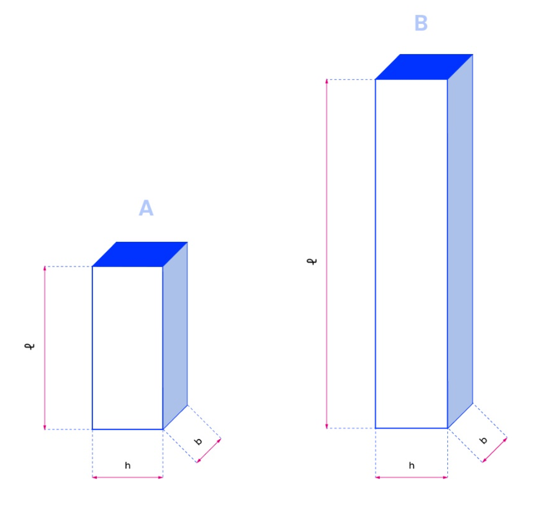
The characteristic dimensions of the specimens are shown below:
- Compressive strength: (b) 12.7mm x (h) 12.7mm x (ℓ) 25.4mm;
- Compression module: (b) 12.7mm x (h) 12.7mm x (ℓ) 50.8mm.
All samples were tested using a universal testing machine (Zwick / Roell Z020, Germany) according to ASTM D695-15.
Before proceeding with the test, the samples were conditioned at 23 ± 2 ° C and 50 ± 5% relative humidity for 40 hours. Subsequently, the width (h) and thickness (b) of the sample at different points along its length were measured by means of a centesimal digital caliper (Mitutoyo Corp, Japan), calculating the minimum value of the cross-section (A).
Average Sample Dimensions
|
Speciment
Type |
h [mm] |
b [mm] |
A[mm2] |
|
CPEEK Compression modulus |
12,71
± 0,03 |
12,64
± 0,27 |
160,87
± 3,48 |
|
CPEEK Ultimate
compression strength |
12,72
± 0,20 |
12,72±
0,31 |
161,87±
4,26 |
Compression Test: The samples were placed between the compression tool surfaces, ensuring that the symmetry axis of the sample coincided with the piston axis. The test speed was set to 1.3 mm/min.
Results for Carbon PEEK: The behavior of Carbon PEEK shows a Hookean (linear) trend with an average elastic modulus (Ec) of 4.8 ± 0.2 GPa and a compressive strength (σM) of 207 ± 8 MPa, with peaks up to 215 MPa. The statistical dispersion of the data is extremely low both along the Z coordinate and in the XY plane. (Figure 6; Figure 7)
Conclusions
The study demonstrated that the compressive mechanical properties of Carbon PEEK samples do not vary significantly with the position in the printing volume of the ARGO 500. The strength and modulus properties were consistent with slight variations, confirming the objective of mechanical property independence from the printing position. Specifically, the modulus values recorded for Carbon PEEK are 29% higher than those of equivalent samples produced by injection molding.
For the complete study, click here. For Roboze’s material library and data sheets, click here.
